
Nitrogen-Vacancy Magnetometry
Nitrogen-Vacancy (NV) Magnetometry is a novel technique used to precisely measure the magnetic fields of a sample. It relies on an "imperfection" of a diamond's crystal lattice, where one pair of carbon-carbon bonds is replaced with a single nitrogen molecule. By forming a nitrogen-vacant cavity, also called a color center, unique properties of the valence electron can be utilised. Under the right conditions and with the help of lasers, the electron can become especially sensitive to magnetic fields. This property yields extraordinary responsiveness even under ambient conditions and allows researchers to explore nanoscale structures and processes in their sample.
To understand how an NV magnetometer works, two points must first be discussed. The first is the lattice structure of a diamond, which will help explain the unique role of nitrogen and a neighboring vacancy. The second is the quantum spin states and energy levels at which the NV- system can exist. This will help explain how lasers are used to harness the unique fluorescence properties of the NV- center and their irregularities created by the presence of a magnetic field.
The NV Cavity in a Lattice Structure of a Diamond
A conventional diamond consists of a lattice structure where each carbon atom is connected to another at a 109.5 degree angle. They connect through bonds formed by the sharing of valence electrons between neighbouring carbons. Each carbon contributes one electron to a covalent bond, forming four bonds per atom.
NV magnetometers use the same carbon lattice structure, with one exception. A pair of carbon atoms is replaced with a single nitrogen atom. Hence, the location where the neighbouring carbon ought to be remains vacant. Nitrogen, being the seventh element on the periodic table, has five valence electrons. In its ground state, three of these electrons form covalent bonds with the three neighbouring carbons (as the fourth location is now vacant). The remaining two electrons form a lone pair.
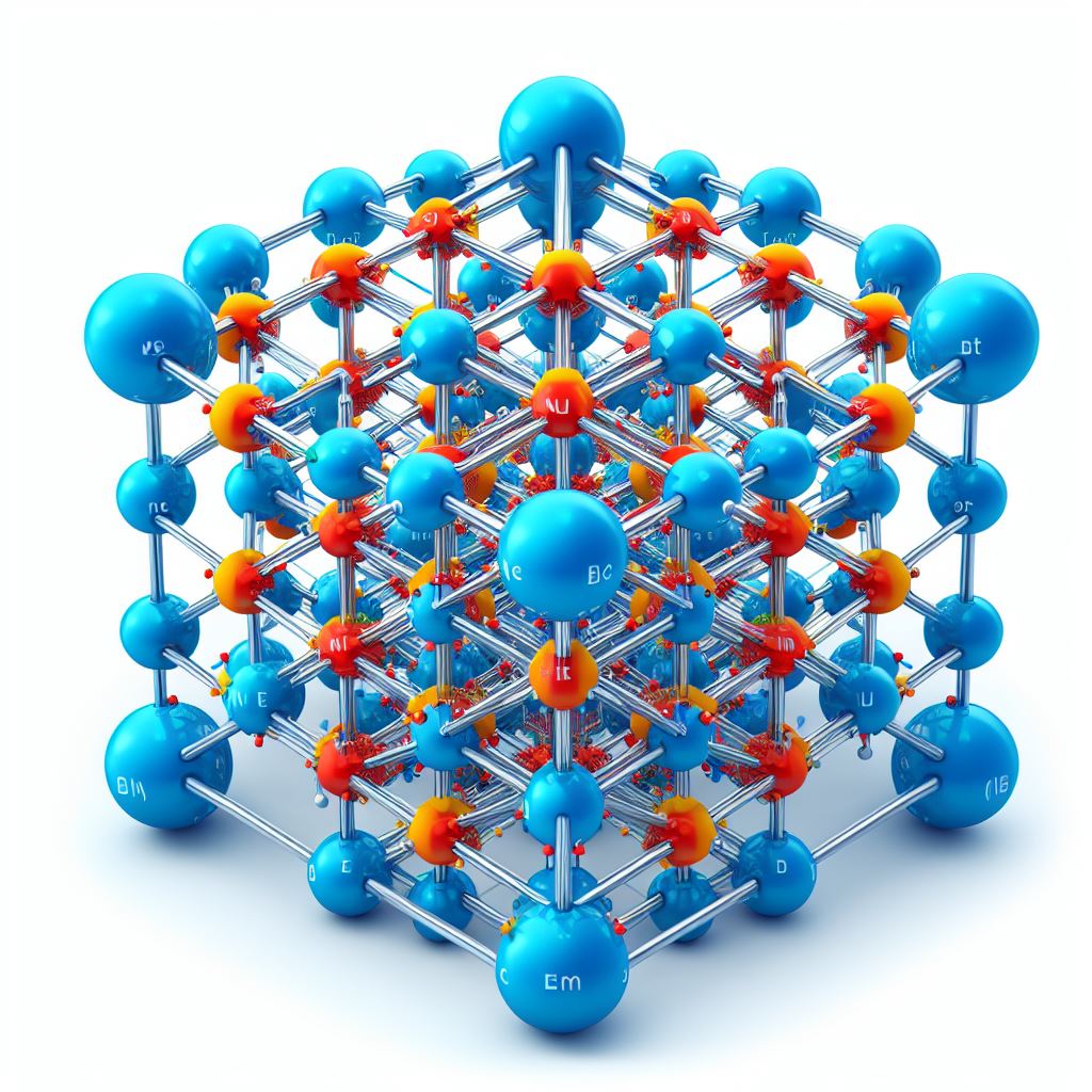
The vacancy of the NV center is essentially a missing carbon atom, leaving a ‘hole’ in the lattice (Figure 1). Two of the three carbon atoms surrounding the vacancy end up sharing a pair of electrons while the remaining electron moves towards the vacancy. The two electrons from the nitrogen’s lone pair remain localised near nitrogen. This results in one electrons in the vacancy and a NV0 net charge. However, the NV center is most stable in the negatively charged state (NV-). Therefore, it requires an extra electron, bringing the total to two. This extra electron comes from the environment which acts as an electron donor to the NV center.

Figure 1. NV Lattice Structure showing the three carbon and one nitrogen atoms surrounding the vacancy.
Electron Spin States and Energy Levels in the NV Center
The two electrons within the NV- center form a system in which they can exist in multiple spin states: |0>, |−1> and |+1>. While the system as a whole can be either in the triplet ground state (3A) or the triplet excited state(3E). Between these two triplets there is an intermediate singlet state(1A), which can be used during transition between 3A and 3E.
The un-initialized NV- system exists predominantly in the 3A triplet, in the spin state of |0>. This is the lowest energy level, and thus the most stable state. Above it we have the |+1> and |-1> states, which are degenerate (i.e., they have the same energy). However as they are less stable, an electron in these states would only exist for around 500 μs. This is also known as spin coherence, and it affects the quality of the signal that can be obtained from this system.
The energy level of |0> is unaffected by external factors. However, the |±1> state is sensitive to magnetic fields. Once an external magnetic field is applied the degenerate states split into energetically distinct |−1> and |+1>. The behaviour of splitting spectral lines with a static magnetic field, observed due to the separation of formerly degenerate energy levels, is known as the Zeeman effect (Figure 2).
In the presence of a magnetic field, going down from the 3E energy level, both |+1> and |-1> states will haven affect fluorescence behaviour. Therefore, by measuring fluorescence intensities as the system changes spins states and triplets, we can perceive the magnetic field along the NV- axis. This is the basis for magnetic field sensing with NV centers.

Figure 2. Energy level diagram of the NV center with and without an external magnetic field.
Fluorescence Principle in NV Magnetometry
The NV system works by changing the fluorescence intensity as a response to external magnetic fields. Unlike typical fluorescence microscopy methods, where the fluorescence signal is proportional to the number of molecules present, in NV magnetometry it is the dip in fluorescence signal that informs researchers of the magnetic field and its strength. This principle is discussed below.
The electron in a NV- system usually exists in either the |0> or |±1> states of the 3A level. The system is initialised by a process called optical pumping using a 532 nm laser. The energy gap between the spin levels of the ground and excited states is identical. This means that an electron in the ground state |0> can only jump to |0> of the 3E state. This also applies to jumps between the |±1> spin state from the ground to excited states. In other words, during optical excitation the spin of an electron is conserved.
When the electron moves down from the excited triplet |0> spin state to the ground state |0>, it emits a photon corresponding to 637 nm (red) light. The same holds true going down the triplet when electrons are in |±1> spin states. However, the latter transition happens only around 70% of the time. The other 30% occur without conserving the spin and instead, relying on the intermediate state. In those cases, because of non-radiative relaxation, no photons are emitted (Figure 3). This difference in fluorescence intensity, influenced by external magnetic fields, allows for a technique called Optically Detected Magnetic Resonance, which enables researchers to accurately measure magnetic fields.
Microwaves in NV Magnetometry
An effective magnetometry system incorporates control of both excited states and spin states. In other words, there are two paths an electron can take within an NV- system. The first one discussed above is the leap between the excited and ground states, while maintaining the spin state. The second one is the change of spin states such as moving between |0>, |−1> and |+1>. Energy levels can be navigated with the help of the aforementioned 532 nm laser light source (as the spacing corresponds to the energy of a 532 nm photon). The difference in energy between spin states is much smaller, corresponding to that of a microwave. Therefore, microwave radiation can be used to bias the system from |0> towards |±1> spin states (Figure 3).
In the absence of a magnetic field a 2.87GHz frequency pulse is sufficient to raise an electron in the 3A |0> state to a 3A |±1> spin state (as they are degenerate). A magnetic field will create separation between the |-1> and |+1> states. This happens because spin "up" (|+1>) is parallel to the magnetic field and thus the virtual energy level at which the electron resides is further raised, while the spin "down" (|-1>) is antiparallel and is attenuated closer to the ground state. Therefore, a relatively lower frequency will be required for the jump from |0> to |-1> and a higher frequency for |0> to |+1>. This difference in frequencies will be proportional to the strength of the magnetic field (Figure 3).
Understanding the Optical Signal
The bias of using the intermediate energy level when moving back to the ground state from the |±1> spin state also applies in cases where these two spin states are separated. However, now that these states are separate it is possible to observe a dip in fluorescence twice. In fact, the strength of the magnetic field can be measured by the frequency needed to change the spin state of the electron to |-1> or |+1>. The diagram below shows how the spacing of the two dips is proportional to the strength of this field, while the decrease in fluorescence intensity remains unaffected (Figure 3).

Figure 3. Top Row: Non-radiative decay at the NV- center. Middle Row: Visualisation of fluorescence intensity with respect to microwave frequency used. Bottom Left: The order in which NV Magnetometry steps are taken. Bottom Right: Impact of magnetic field's strength on spin state separation.
Capabilities and Applications
At room temperature the spatial resolution attainable can reach 5 nm. This is sufficient to image single molecules and dynamic cellular processes. To obtain such resolution complete contact with the sample is necessary. Moreover, the NV- axis must be aligned with the objects magnetic field, otherwise the Zeeman effect will not take place.
NV Magnetometry is particularly attractive as it does not require intricate cooling mechanisms or bulky optical setups. Moreover, developments in manufacturing allow for both the NV crystal and the imaging system itself to become ever smaller. Proposals for handheld devices are published regularly. Therefore, it is likely a matter of time before magnetometers become a commonplace tool in biotechnology and material science laboratories.
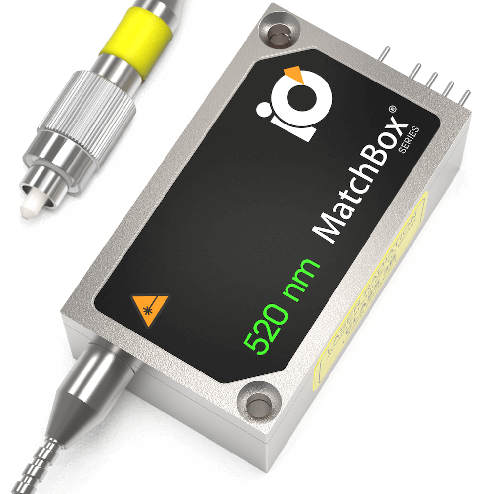
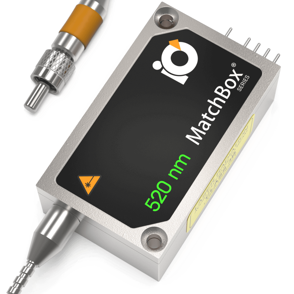
At Integrated Optics, our world's smallest lasers are exactly what you need for your magnetometry applications. Their footprint is perfect for hand held systems. They carry sufficient power to be incorporated into compact stationary devices. With integrated TEC and electronics, complete control is achieved while maintaining the size of a matchbox.
Relevant Products
520 nm SLM Laser
Spectral line width FWHM, pm: 0.1
Output power, mW: 15
Power stability, % (RMS, 8 hrs): 0.05
Intensity noise, % (RMS, 20 Hz to 20 MHz): 0.5
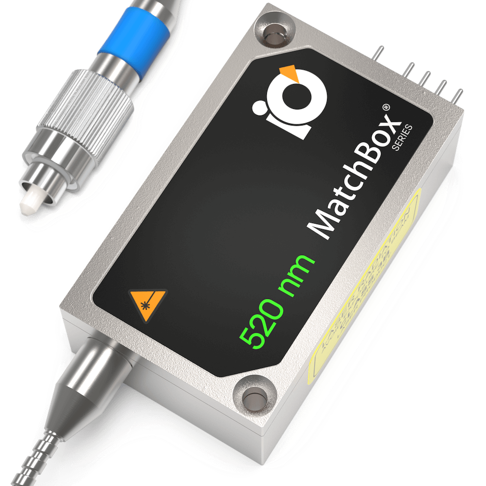
520 nm SLM Laser
Spectral line width FWHM, pm: 0.1
Output power, mW: 15
Power stability, % (RMS, 8 hrs): 0.05
Intensity noise, % (RMS, 20 Hz to 20 MHz): 0.5
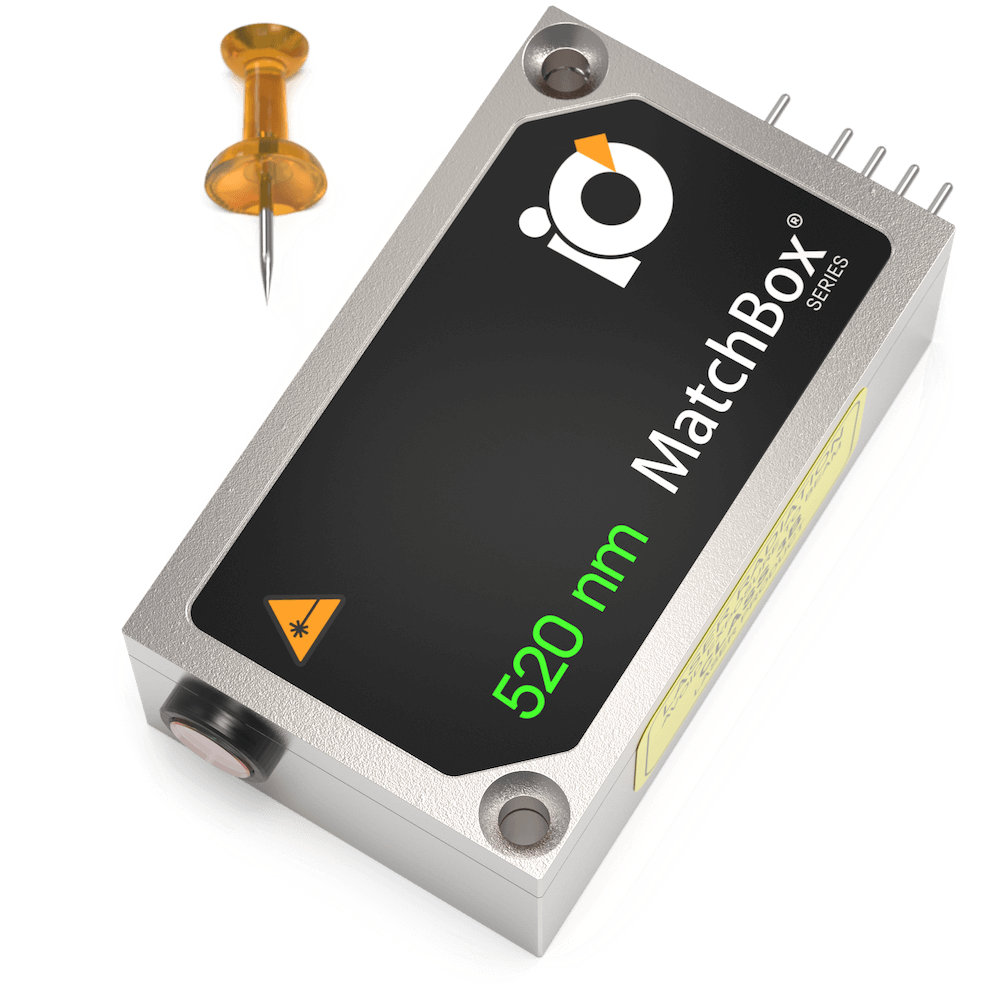
520 nm SLM Laser
Spectral line width FWHM, pm: 0.1
Output power, mW: 40
Power stability, % (RMS, 8 hrs): 0.05
Intensity noise, % (RMS, 20 Hz to 20 MHz): 0.5
520 nm SLM Laser
Spectral line width FWHM, pm: 0.1
Output power, mW: 30
Power stability, % (RMS, 8 hrs): 0.05
Intensity noise, % (RMS, 20 Hz to 20 MHz): 0.5
Publications
New Journal of Physics:
Physical Review B: