About MatchBox Series
The MatchBox Series is an award winning, powerful, and widely configurable laser platform, encompassing CW lasers, up to 4-wavelength diode lasers, and Q-Switch nanosecond lasers. It offers the simplicity of integration and selection of >200 products within the series.
- Unified footprint of 50x30 mm2
- Single control software
- UART/USB/RS232 control interface options
- Hands-free operation
- Shock resistant >80G
- Unified footprint of 50x30 mm2

There are more than 150 CW single-wavelength laser configurations in the MatchBox® product family. Both direct diode and DPSS laser principles are implemented in the World’s smallest MatchBox® footprint. Single-frequency (or singe-longitudinal mode) options are available for the majority of wavelengths.
Features
- SM/PM/MM fiber coupling options
- Ultra-compact All-in-One design*
- Thermally stabilized optics
- Monolithic design
- Hermetically sealed
- Automatic power control
- +5VDC input voltage (voltage is upconverted internally to make it suitable for various laser diodes)
*The laser head includes optics and driving electronics within a single enclosure.
Advantages
- Easy to integrate (smallest enclosure on the market)
- Convenient to arrange in the proximity of a working area
- Standard Package (MatchBox®)
- User-friendly software with multiple parameter monitoring
- Low power consumption in standby-mode (important for battery-powered applications)
- Excellent beam pointing angle and beam position accuracy
- High cooling capacity
- Rugged enclosure
- Operational hours counter
- On/Off cycle counter
- Smart over-heat protection
- Black surface finish absorbs reflections
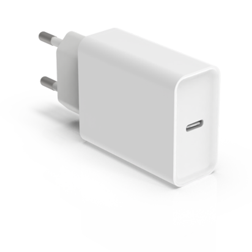
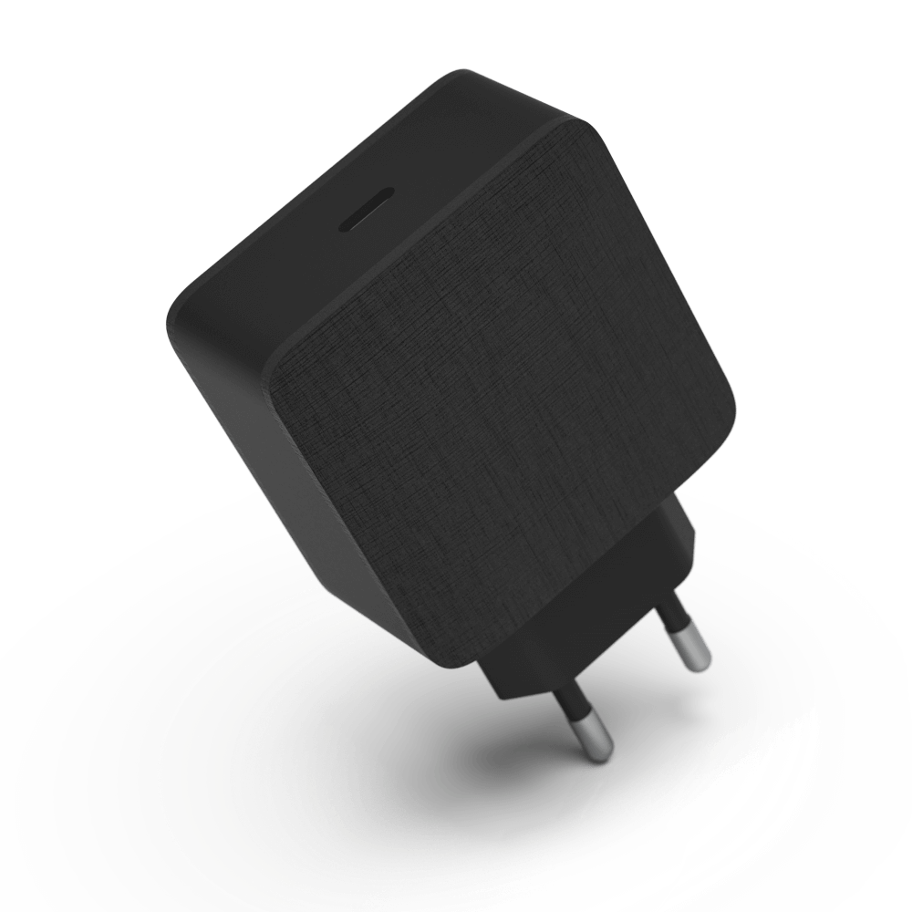
- Power delivery (PD) based power supplies
- Variety of accessories
- Space-saving pinhead connector
What's in the Box?
- Laser Source (integrated power electronics in the same enclosure)
- One thermal film. If a laser is sent mounted on a heatsink with a thermal film, an additional 1 g of thermal grease is included.
- 2 screws of M2.5x20 mm for fixing the laser to a mounting plate. Tightening torque 0.25 - 0.35 N·m
- Hex key: 1.5 mm; BN:1169; DIN:911
Control Interface
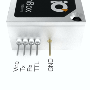
MatchBox® series lasers feature a Universal Asynchronous Receiver/Transmitter (UART) controller interface. The pinout is explained below - separately for diode and DPSS lasers.

Diode Laser with a regular spectrum
- Tx and Rx pins are used for communication, error read-out and change of parameters
- GND pin is common to the enclosure
- Vcc pin is used for +VDC power
- TTL pin can have two purposes: TTL ON/OFF digital modulation of the laser (in case of regular diodes) or control of a variable speed fan*** (in case of wavelength-stabilized diodes)
DPSS / narrow spectrum diode / high power diode lasers
- Tx and Rx pins are used for communication, error read-out and change of parameters
- GND pin is common to the enclosure
- Vcc pin is used for +VDC power
- FAN ctrl. pin is used for variable speed control of a fan***

Break-out-Box Explanation
The Break-out-Box (sold separately) contains UART-USB converter circuit and conventional connection ports in a robust anodized aluminium housing.
- Data USB-micro port is used for communication with a computer.
- Interlock has two pins - INT-GND and INT. When the pins are shortened with an interlocking loop, the laser can be operated.
- TTL modulation signal wires shall be connected to TTL and GND slots.
- Power USB-C port is used for the provision of PD (Power Delivery) power. The break-out box requests +9VDC or +12VDC from the power supply and convert it to +5VDC, thus ensuring a reliable and stable voltage supply to the laser.
- FAN and +5V slots are compatible with all our fan-cooled heat sinks. FAN slot is used for fan-heatsink GND.

Software Interface
The MatchBox® laser control software is used for checking preset parameters, such as the max. laser diode current, target temperatures for laser internal diode, laser body, and actual measured values of these parameters, as well as the load percentage of the Peltier elements. This is very helpful for laser diode age tracking and other troubleshooting actions.
The software window is divided into four segments. Each segment represents a different control field of the MatchBox® laser:
- Right above the first segment, you can see a port number, an item name, a serial number, and a hardware version.
- The first segment is used for turning on the power of the laser, but the laser isn’t emitting light. A warning sign can be seen in the segment too. It indicates whether the laser power is on or off. The next parameter seen in this segment is the operating mode of the laser.
- The second section of the software window is used for laser power control. You can enable or disable laser radiation, change units of optical power setting. This column also shows the current of the laser diode - its maximum value and the actual current. In the status bar, if the circle is green, the laser is emitting light, if it is grey, laser radiation is turned off.
- The third section is for controlling operation modes of the laser - ACC/APC, Auto-Warm-up, Auto-Start.
- The last section is for observing the temperature of the laser body and the laser internal diode, cooler status, fan load, and laser voltage.

The Multi-Wavelength MatchBox laser is a configurable turnkey emitter/detector system for life sciences, sorting, and particle analysis applications. It has a standard MatchBox footprint and is compatible with a rich set of MatchBox® accessories.
Features
- 2 to 4 individually controllable laser diode drivers
- Ultra-compact All-in-One design*
- Thermally stabilized optics
- Monolithic design for hands-free operation
- Fiber coupling and beam shaping options
- Automatic power control
- PD (power delivery) compatible USB-C power input (in breakout box)
*The laser head includes optics and driving electronics within a single enclosure.
Customization
- Easy to integrate (smallest enclosure on the market)
- The desired set of 2 to 4 emitters/detectors
- Customer specified set of dichroic mirrors, clean-up and blocking filters
- Common output beam shaper, such as line generator, DOE, focusing optics, etc.
- Fiber end collimators and beam shapers
- Pre-programmed modulation patterns
- Customer specified beam diameter and divergence
- Customer specified fiber pigtail
- Amplifier circuits for avalanche photodiodes
Novel Product Concept
The multi-wavelength MatchBox® laser includes from 2 to 4 laser diode drivers and digital control electronics, which allows smart control and diagnostics of the complete module.
The laser unit is designed as an integration-ready electro-optics unit, which can be connected to a control mainboard and power supply of an instrument. This way the laser/detector unit provides unprecedented compactness and functionality. Thus mass production of multi-wavelength instruments becomes much easier and faster.
Communication protocol
MatchBox® series lasers feature a Universal Asynchronous Receiver/Transmitter (UART) controller interface. The pinout of MatchBox Combiner is an expanded version of the standard MatchBox® pin-out. The lower row of pins is the same as for single-wavelength lasers, while the second (upper) row is added for individual TTL modulation of each laser diode installed in the combiner.
Break-out-Box
A 'Break-out-Box' is used for converting UART into a USB protocol. The converter chip for USB is 'Silicon Labs CP2102'. Additionally, the break-out-box of the multi-wavelength MatchBox laser is equipped with the necessary circuit for communication and PD type (power delivery) power supplies.

Pins for Tight Integration
10 pins at the back of the laser combiner provide full access to the complete functionality of the combiner.
Pins are located at the backside of the enclosure and distributed in a way, which allows for implementing a mechanical reverse lock.
Prerequisites for such integration are a microcontroller mainboard supporting UART communication, 12V or 9V at 1.5 A (Power delivery) power supply, and 2 to 4 TTL channels for an individual on/off digital modulation of each laser diode.

Pin-out Explained
- L1 on/off diode TTL, 5V tolerant and 3.3V compatible
- L2 on/off diode TTL, 5V tolerant and 3.3V compatible
- GND ground connected to the laser body
- L3 on/off diode TTL, 5V tolerant and 3.3V compatible
- L4 on/off diode TTL, 5V tolerant and 3.3V compatible
- GND ground connected to the laser body
- Progr. pin is used to control fan of a heatsink, based on laser body temperature.
- Rx UART communication, 5V tolerant
- Tx UART communication, 5V tolerant
- Vcc 9-12V at 1.5 A, or PD (Power delivery) compliant power supply.

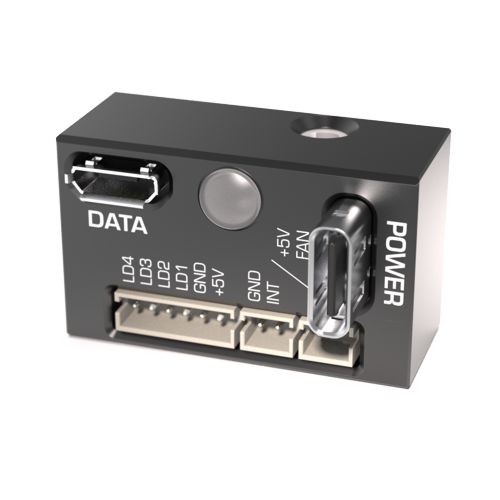
Break-out-Box Explained
The Break-out-Box contains UART-USB converter circuit and conventional connection ports in a plastic housing.
- Data USB (left) is used for communication with a PC
- Interlock occupies two pins: INT-GND and INT. When the pins are shortened with an interlocking loop, the laser can be operated
- L0, L1, L2, L3 are all digital TTL modulation pins for corresponding laser diode channels or read-out pins for photodetectors, depending on product configuration.
- Power input USB-C (right) connector is used for connection to a PD (power delivery) compatible power supply.
- Fan ctrl. connector (not visible, on the right side of the breakout box) is compatible with all our fan-based heatsinks.
Software Interface
The MatchBox® laser control software is used for checking preset parameters, such as the max. laser diode current, target temperatures for laser internal diode, laser body, and actual measured values of these parameters, as well as the load percentage of the Peltier elements. This is very helpful for laser diode age tracking and other troubleshooting actions.
The software window is divided into four segments. Each segment represents a different control field of the MatchBox® laser:
- Right above the first segment, you can see a port number, an item name, a serial number, and a hardware version.
- The first segment is used for turning on the power of the laser, but the laser isn’t emitting light. A warning sign can be seen in the segment too. It indicates whether the laser power is on or off. The next parameter seen in this segment is the operating mode of the laser.
- The second section of the software window is used for laser power control. You can enable or disable laser radiation, change units of optical power setting. This column also shows the current of the laser diode - its maximum value and the actual current. In the status bar, if the circle is green, the laser is emitting light, if it is grey, laser radiation is turned off.
- The third section is for controlling operation modes of the laser - ACC/APC, Auto-Warm-up, Auto-Start.
- The last section is for observing the temperature of the laser body and the laser internal diode, cooler status, fan load, and laser voltage.

The MatchBox® Series includes several variants of pulsed lasers. High peak power and short pulse duration lasers are based on a passive Q-Switch laser technique, which has the benefit of fixed pulse energy. This is very convenient for a variety of applications ranging from material processing to LiDAR. Matchbox® lasers show that small dimensions and high performance are not mutually exclusive.
Features
- Ultra-compact All-in-One design*
- Thermally stabilized optics
- Monolithic design
- Hermetically sealed
- Automatic power control
- 2nd Harmonic generation
- +12VDC input voltage (voltage is upconverted internally to make it suitable for various laser diodes)
*The laser head includes optics and driving electronics within a single enclosure.

Software Interface
The MatchBox® laser control software is used for checking preset parameters, such as the max. laser diode current, target temperatures for laser internal diode, laser body, and actual measured values of these parameters, as well as the load percentage of the Peltier elements. This is very helpful for laser diode age tracking and other troubleshooting actions.
The software window is divided into four segments. Each segment represents a different control field of the MatchBox® laser:
- Right above the first segment, you can see a port number, an item name, a serial number, and a hardware version.
- The first segment is used for turning on the power of the laser, but the laser isn’t emitting light. A warning sign can be seen in the segment too. It indicates whether the laser power is on or off. The next parameter seen in this segment is the operating mode of the laser.
- The second section of the software window is used for laser power control. You can enable or disable laser radiation, change units of optical power setting. This column also shows the current of the laser diode - its maximum value and the actual current. In the status bar, if the circle is green, the laser is emitting light, if it is grey, laser radiation is turned off.
- The third section is for controlling operation modes of the laser - ACC/APC, Auto-Warm-up, Auto-Start.
- The last section is for observing the temperature of the laser body and the laser internal diode, cooler status, fan load, and laser voltage.

Heatsinks
A low profile forced-air cooler has an integrated centrifugal fan. Very efficient for dissipation of a large amount of excess heat.
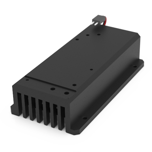
A compact TEC-cooled mounting adapter plate is a great cooling unit for good thermal and mechanical stability requiring lasers and setups.

A cost-efficient high-capacity forced air-cooler. It is used mainly for direct diode and low power DPSS lasers.
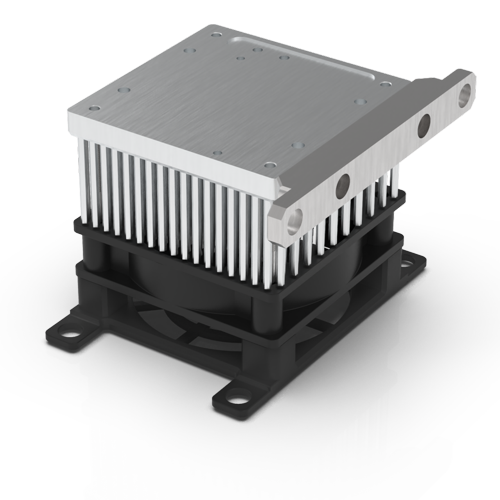
A very efficient, TEC and fan-based, cooler. It is used mainly with high-power DPSS and high parameter stability requiring lasers.

Code Structure

