Total Internal Reflection Fluorescence (TIRF) Microscopy

TIRF microscopy is a powerful optical technique used primarily in the field of cell biology. It allows for the observation of phenomena occurring at the interface between a cell and a substrate, such as cell adhesion, membrane dynamics, and signal transduction events.
Principle of Total Internal Reflection
The principle behind TIRF microscopy is the phenomenon of total internal reflection (TIR). TIR occurs when light travelling in a medium with a higher refractive index (n1) hits the boundary with a medium of lower refractive index (n2) at an angle greater than the critical angle (θc). The critical angle can be calculated using Snell’s law:
θc = arcsin(n2⁄n1)
When this happens, all the light is reflected back into the medium with the higher refractive index, and none of it is refracted into the second medium. However, an electromagnetic field, called an evanescent wave, does penetrate a short distance into the second medium. This evanescent wave decays exponentially with distance from the interface. This property yields greater specificity by stimulating only a small fraction of the sample in the z axis, thereby allowing for greater resolution.
Evanescent Wave
An evanescent wave refers to a standing wave in the nearfield region. It originates at the boundary between two interfaces. The distance it extends approximately depends on the wavelength and angle of incidence, on average it is around a third of the incident wave’s wavelength. The Effective Penetration Depth is the distance where 37 % of the initial intensity (compared to the interface) of the evanescent wave remains available. This area contains energy that is temporarily held in a reactive field when light encounters the boundary. In other words, the evanescent wave stores this energy by contributing to the electromagnetic (EM) field in a small area around the boundary (Figure 1).

Figure 1. Illustration of an Evanescent wave generated at the interface of two surfaces.
The reason why even under conditions of ‘total’ internal reflection a component of the EM field extends beyond the boundary of our interface is explained by Maxwell’s equations. In essence, the tangential components of the EM field cannot be discontinuous at the boundary. Therefore, that field decreases exponentially in strength starting from the interface of the two surfaces. By doing so it satisfies the continuity and conservation of energy conditions. The evanescent wave persists only while under TIR conditions and ceases the moment they are no longer met. Unlike the reflected light, which would propagate forward indefinitely until blocked by an obstacle, the standing wave vanishes with the absence of light reflecting off the interface.
Like with monochromatic light, an evanescent wave can excite fluorophores and produce fluorescence. This process is called evanescent wave excitation which results from the oscillating nature of this field. It is important to note that this field oscillates at the same frequency as incident light. The wave’s electric field interacts with the electrons of a fluorophore, exciting them to a higher energy state. The field induces a dipole moment in the fluorophore and, in principle like a microwave, excites the electrons. When they return to their ground state, a photon is emitted, resulting in the process known as fluorescence, which we have discussed in a different article.
TIRF Microscope Setup
In a TIRF microscope setup, a laser beam is strategically directed towards a prism, typically made of quartz, which interfaces with the sample. The angle of incidence of the laser light at the boundary between the prism and the sample is carefully adjusted to be greater than the critical angle, a condition necessary to induce total internal reflection. Upon reflection, an evanescent wave is formed. This wave extends into the sample, but its influence is limited to a very short distance, typically less than 200 nm (Figure 2). This shallow penetration depth ensures that only fluorophores in close proximity to the interface are excited, minimizing background fluorescence and improving image contrast.

Figure 2. A simplified diagram of the optical components in a TIRF Microscope.
The excited fluorophores emit fluorescence in response to the evanescent wave. This fluorescent light passes through the cover slip and immersion oil to reach the objective. The objective is designed to capture as much of this emitted light as possible, thereby maximizing the signal-to-noise ratio. The captured light is then directed towards the detector, where it is converted into an electrical signal. This signal is subsequently processed and interpreted by the electronic components of the laser system, resulting in a high-resolution image of the sample. This process allows for selective imaging of events at the cell membrane with minimal interference from intracellular components.
Like other microscopy systems, TIRF microscopy relies on the principles of optics and fluorescence to generate images. Frequently, several types of fluorophores are used to discern multiple unique structures, therefore, a collection of lasers covering different parts of the spectrum are incorporated. In these cases, the variable depth of the effective evanescent field comes into play. When keeping the incident angle constant the field is more shallow for shorter wavelengths and penetrates deeper as the wavelength increases. This may causes issues in imaging depth; unevenly excited fluorophores will skew the perceived spatial distribution and localisation of structures/processes of interest. These systems often address such discrepancies by changing the angle by a factor appropriate to compensate for a given wavelength. Doing so keeps the superior axial resolution and reduced background fluorescence, making it excellent to observe surface phenomena in biological systems.
Advantages of TIRF Microscopy
One of the key advantages of TIRF microscopy is its ability to achieve very high axial resolution, much higher than can be achieved with conventional fluorescence microscopy techniques. This is because the evanescent wave decays rapidly with distance from the interface. By doing so it provides a natural optical sectioning. Moreover, the evanescent wave itself does not contribute to optical noise that could come from excitation laser light. For these reason TIRF could be considered a Super-Resolution Microscopy (SRM) technique as it can image below the diffraction limit. However, because the resolution is limited to the z axis, it is often incorporated with other SRM techniques for better results.
Because the excitation occurs only a short distance into the sample, TIRF microscopy has the unique ability to selectively illuminate and excite fluorophores localised on the surface and inner outskirts of the cell. This makes it ideal for studying processes receptor-ligand interactions, membrane dynamics, and cell adhesion processes.
Relevant Products
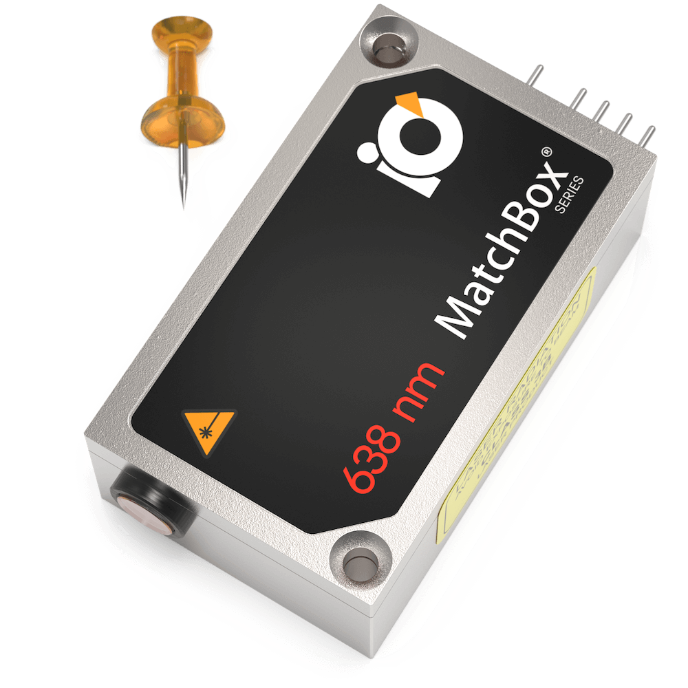
638 nm Laser
Spectral line width FWHM, nm: 0.7
Output power, mW: 170
Power stability, % (RMS, 8 hrs): 0.05
Intensity noise, % (RMS, 20 Hz to 20 MHz): 0.25
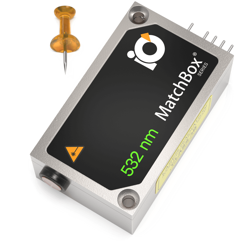
532 nm Laser
Spectral line width FWHM, nm: 0.1
Output power, mW: 200
Power stability, % (RMS, 8 hrs): 0.1
Intensity noise, % (RMS, 20 Hz to 20 MHz): 5
Multi-Wavelength Laser
488 nm - 40
561 nm - 50
638 nm - 130
Power stability, % (RMS, 8 hrs): 0.2
Intensity noise, % (RMS, 20 Hz to 20 MHz): 0.5

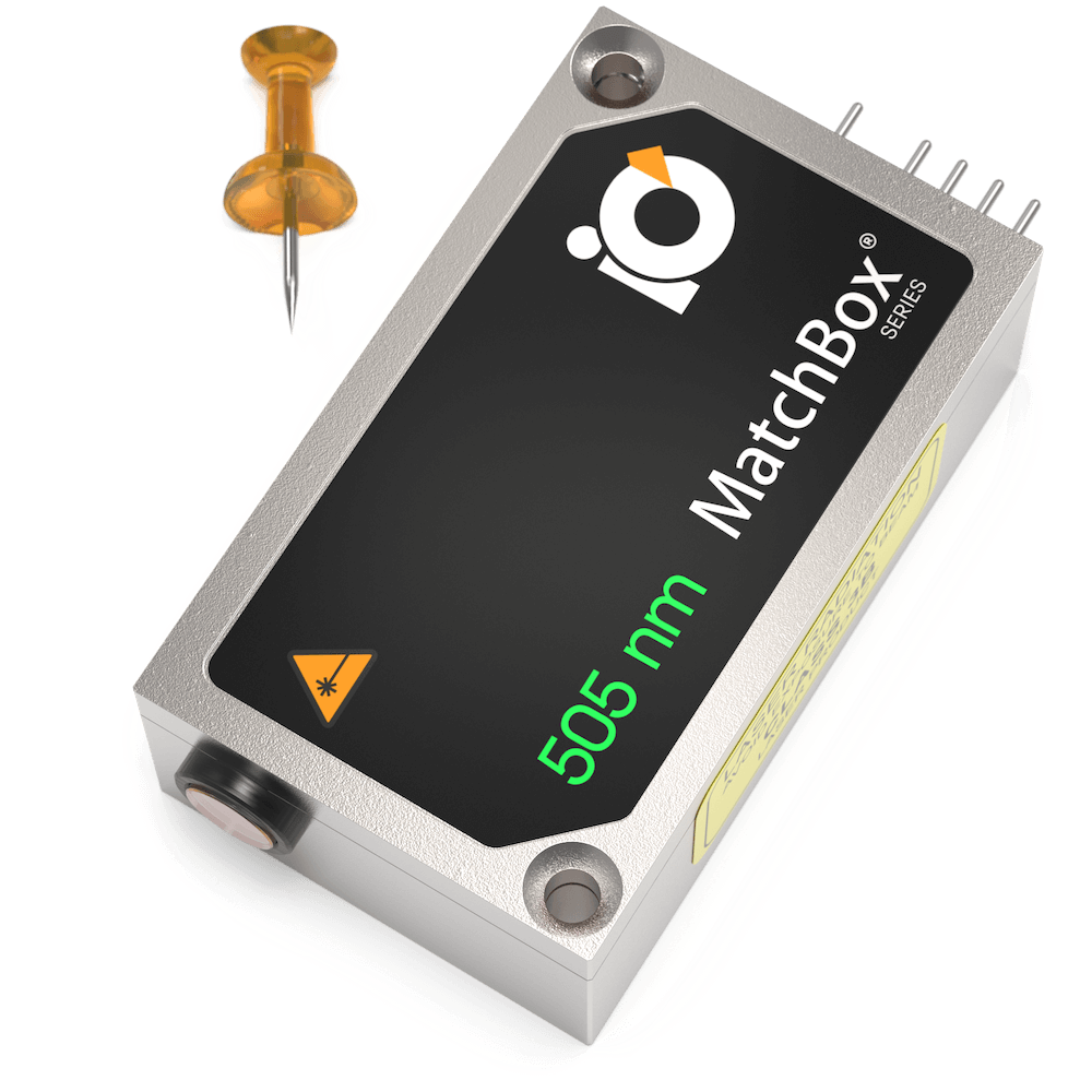
505 nm Laser
Spectral line width FWHM, nm: 0.7
Output power, mW: 60
Power stability, % (RMS, 8 hrs): 0.03
Intensity noise, % (RMS, 20 Hz to 20 MHz): 0.5
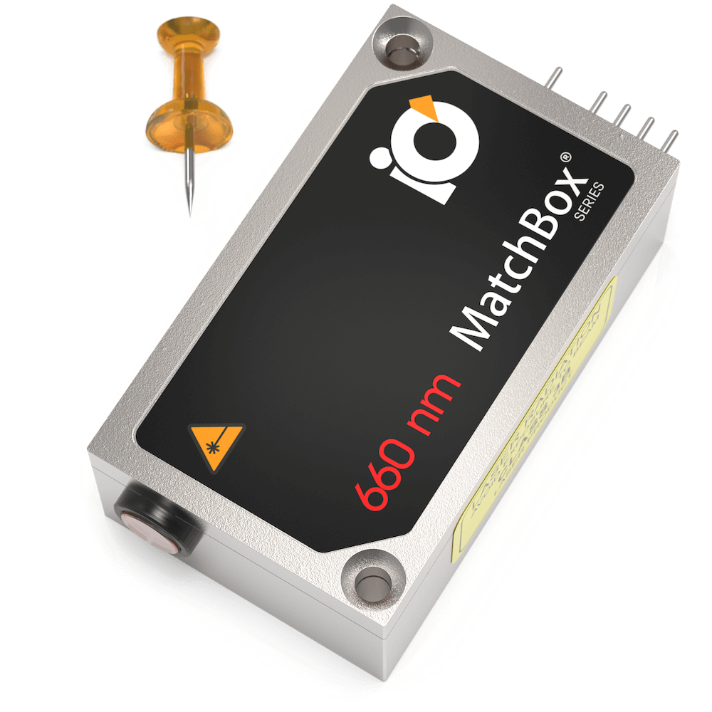
660 nm Laser
Spectral line width FWHM, nm: 0.7
Output power, mW: 110
Power stability, % (RMS, 8 hrs): 0.05
Intensity noise, % (RMS, 20 Hz to 20 MHz): 0.2
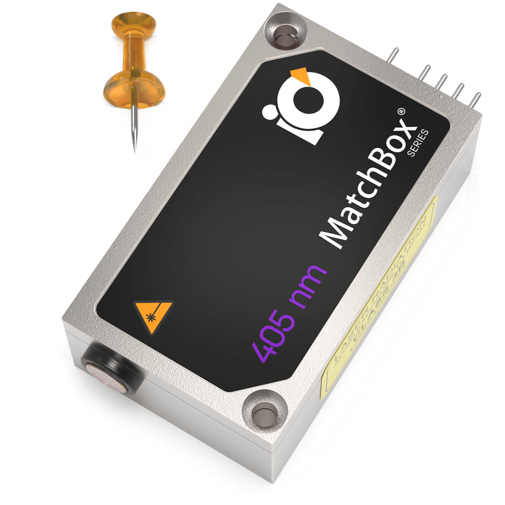
405 nm Laser
Spectral line width FWHM, nm: 0.5
Output power, mW: 180
Power stability, % (RMS, 8 hrs): 0.1
Intensity noise, % (RMS, 20 Hz to 20 MHz): 0.15
Multi-Wavelength Laser
488 nm - 40
520 nm - 80
638 nm - 130
Spectral line width FWHM, nm: 1
Power stability, % (RMS, 8 hrs): 0.2
Intensity noise, % (RMS, 20 Hz to 20 MHz): 0.5
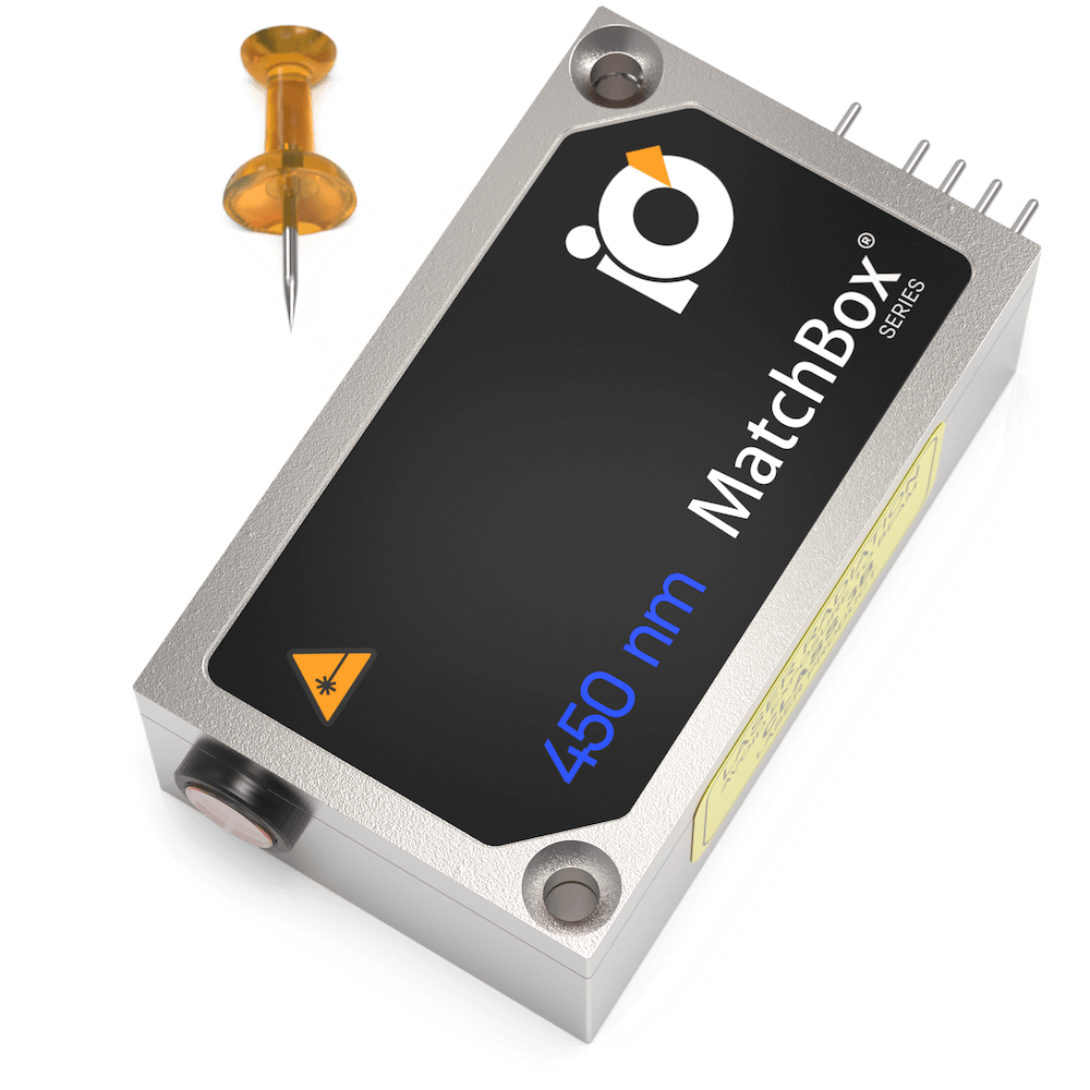
450 nm Laser
Spectral line width FWHM, nm: 0.8
Output power, mW: 60
Power stability, % (RMS, 8 hrs): 0.05
Intensity noise, % (RMS, 20 Hz to 20 MHz): 0.4
